Dust Collection System Information
Designing an efficient dust collection system can be complex, but we have streamlined the process into a few basic steps to help smaller shops and industrial facilities get started.
Important Regulatory Notice
While these steps provide a foundation, please remember that federal, state, and local regulations—as well as codes enforced by Authorities Having Jurisdiction (AHJ)—strictly govern the sales, construction, installation, and use of dust collection systems.
Air Handling Systems (Manufacturers Service Co., Inc.) emphasizes that providing high-quality products and support is our role; however, we cannot guarantee compliance with every specific local regulation. It is the sole responsibility of the purchaser and user to:
- Review all applicable codes (including NFPA and OSHA) prior to purchase.
- Exercise due diligence to ensure the design, installation, and usage of the system are fully compliant.
- Assume responsibility for the final installation safety, as Air Handling Systems cannot assume liability for how the product is installed or used.
In order to start the process we recommend:
- Click link to download our Air Handling Design Guide.
- Click link to review our Tips on Installing your Air Handling System.
- Click link to download our Take off list for Quotes to ease the process of quoting.
- Click link to download our CFM Requirements and Proper Branch Diameter Sizes guide to view proper CFM requirements and branch diameter sizes.
Before you start designing your Air Handling System you need a floor plan of your shop area including the following:- Location of dust producing machines: indicate size & location of dust pick ups on each machine.
- Desired location of dust collector unit.
- Floor to joist measurement.
- Any obstructions that would interfere with the run of the duct.
3. Familiarize yourself with these terms:
- CFM – Air Volume in cubic feet per minute.
- FPM – Velocity of Air in feet per minute.
- SP – Static Pressure. This is expressed in inches water gauge. It is resistance to air at rest in a duct, and is also commonly called “resistance”, “friction”, “friction loss”, or “pressure loss.”
- VP – Velocity Pressure: expressed in inches water gauge. It is kinetic pressure in the direction of flow necessary to cause air at rest to flow at a given velocity.
Calculations
It is best to do the following calculations before you purchase your Dust Collector or the necessary ductwork.
- Duct Velocity
Use the chart below to determine the velocity of your system.Type of Dust Velocity in Branches Velocity in Main Metalworking Dust 4500 FPM 4000 FPM Woodworking Dust 4000 FPM 3500 FPM Other Light Dust 4000 FPM 3500 FPM - Determine the size of each branch
There are several ways to determine the diameter of the branches.- If the machine has a factory installed collar, the manufacturer has determined that the machine needs that size branch under normal circumstances.
- If the machine has a metric diameter outlet, convert it into inches, and round off to the nearest inch. When writing up your parts list you may need to order a custom reducer.
- If the outlet is rectangular you need to determine the equivalent round diameter. When you write up your list use a transition.
- If the branch is smaller than 3″ diameter plan using a reducer near the machinery to increase the branch to 3″. Figure the CFM for 3 “(195 CFM).
Determine CFM requirements for each branch. Under the proper velocity note the CFM of each branch. If working with wood dust, use 4000 FPM in branches ( see above – A) Duct Velocity ).
- Determine Diameter of Main Duct
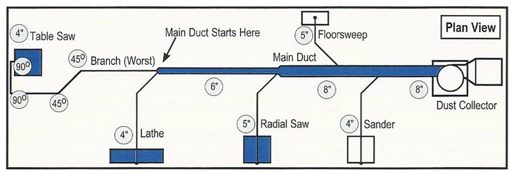
- Determine which machines are your primary machines. A primary machine is the machine(s) that will operate at the same time under the worst conditions. (If you normally operate two machines, but once a week need to operate a third machine at the same time, then you must size your system for all three machines.) We generally highlight the primary machines on the drawing.
- Sizing the Main Trunk Line. When sizing the main truck line start with the primary machine farthest from the duct collector. Run that size duct until the next primary branch enters the main. Increase the main size at that junction to accommodate theCFM total of the two primaries. You will follow this practice all the way to the collector, sizing all primary junctions, to accommodate total CFM of all primaries at that point. Do not increase main duct size when a branch other than a primary enters. Your total CFM requirement is the total of all primary branches. When not using a primary machine you will close blastgate and divert suction to a secondary machine.
Example:
You have 3 primary machines. You have already assigned the branch diameter and CFM requirements. Table Saw, Lathe 4″ Diameter 350 CFM Radial Saw 5″ Diameter 550 CFM A 4″ branch will be run from the Table Saw until it joins with the 4″ branch from the Lathe. At this point your main starts and you need to increase the pipe to handle the combined CFM (350+350 = 700). Using the CFM Chart 1 look up 700 CFM under the appropriate velocity (3500 FPM in the main for wood dust), then look at the corresponding diameter (6″). Run 6″ pipe in the main from the Lathe until the branch of the Radial Saw joins the main.
Here again you need to increase your main to handle the total CFM (700+550=1250 CFM). Using the chart again you will see that 1250 CFM is slightly more than volume for 8″ diameter. Drop back to 8″ diameter so as not to go below transport velocity. Run the 8″ duct in your main from the Radial Saw to your Dust Collector.
If you are installing an indoor re-circulating dust collector you need not calculate any more duct diameters. If you are attaching ductwork to the exhaust side of your duct collector it is accepted practice to use a duct diameter two diameters larger on the exhaust side than on the inlet side, thus minimizing exhaust and duct resistance.
Charts
- Figure System Resistance (SP)
The total static pressure is several factors added together. They are entry loss, dirty filter loss, static pressure of the worst branch duct, static pressure of the main duct, and static pressure of the return duct.- There are more complicated ways to figure the entry loss of your system, but we find it usually equals a loss of 1″ water gauge. (Use 1″ as a constant.)
- If your system has filters, add in 2″ loss. (If you do not have filters add zero).
- The Worst Branch, is the branch with the greatest resistance. The branch with the greatest resistance is usually a smaller diameter with the most lineal footage of pipe elbows. Static pressure of worst branch and main duct can be calculated by using the following Chart 2. Chart 2 is based on 100 feet of pipe; therefore, you have to convert all elbows to an equivalent of pipe.To convert 90° and 45° elbows to equivalent feet of pipe use our Elbow to Straight Pipe Conversion chart. When figuring the feet of pipe count lateral type branches as 45° elbows. Flexhose has a lot of resistance depending on the amount of bends included in the installation. For this reason we suggest you keep hose to a minimum. Multiply your length of flexhose on your worst branch by 3 for equivalent length of straight pipe.
Example: Determine Static Pressure of Worst Branch
Static Pressure (Inches of Water Gauge) in Worst Branch (4″ Table Saw)Description – 4″ Diameter Equivalent to Straight Pipe Straight Pipe 20′ 2 – 90° elbows 12′ 2 – 45° elbows 6′ 5′ flexhose (3x) 15′ Total equivalent straight pipe after conversions 53′
Example: Static Pressure in MAIN DUCT 6″ and 8″
The static pressure of the Main Duct is done the same way, except you figure it out for each diameter in the Main, starting farthest away and working toward the collector.Example: Determine Static Pressure of Worst Branch
Static Pressure (Inches of Water Gauge) in Worst Branch (4″ Table Saw)Description – 6″ Diameter Equivalent to Straight Pipe Straight Pipe 20′ Total equivalent straight pipe after conversions
700 CFM in 6″ diameter = 3.5″ S.P. per 100′
700 CFM in 6″ diameter = .70″ S.P. per 20′20′ Description – 8″ Diameter Equivalent to Straight Pipe Straight Pipe 25′ 2 – 90° elbows 30′ Total equivalent straight pipe after conversions
1,250 CFM in 8″ diameter = 2.4″ S.P. per 100′
1,250 CFM in 8″ diameter = 1.3″ S.P. per 55′
(8″ Diameter runs to self contained Dust Collector)55′ Total Static Pressure: 1″ + 2″ + 3.71″ + .70″ + 1.3″ = 8.71″ S.P. Inches Water Gauge.
System Requirement: 1,250 CFM at 8.71″ SPWG
Summary & Ordering Parts
Once you have determined your Velocity, CFM, and Static Pressure (including resistance for clean air return ducts, if applicable), you are ready to purchase the correct dust collector and components. To generate your materials list, trace your system starting from the collector outward, ensuring you include essential installation accessories such as pop rivets, hangers, strapping, caulking, and couplings.
Ready to Order? You can place your order or get support via phone at (203) 389-9595, email sales@airhand.com or order online.
Recommended Resource: For additional design guidance without complex calculations, we highly recommend reading Woodshop Dust Control by Sandor Nagyszalanczy, which offers practical, shop-tested solutions for building the right system.